LEFOO FS213 Stainless Thermal Electronic Flow Switch
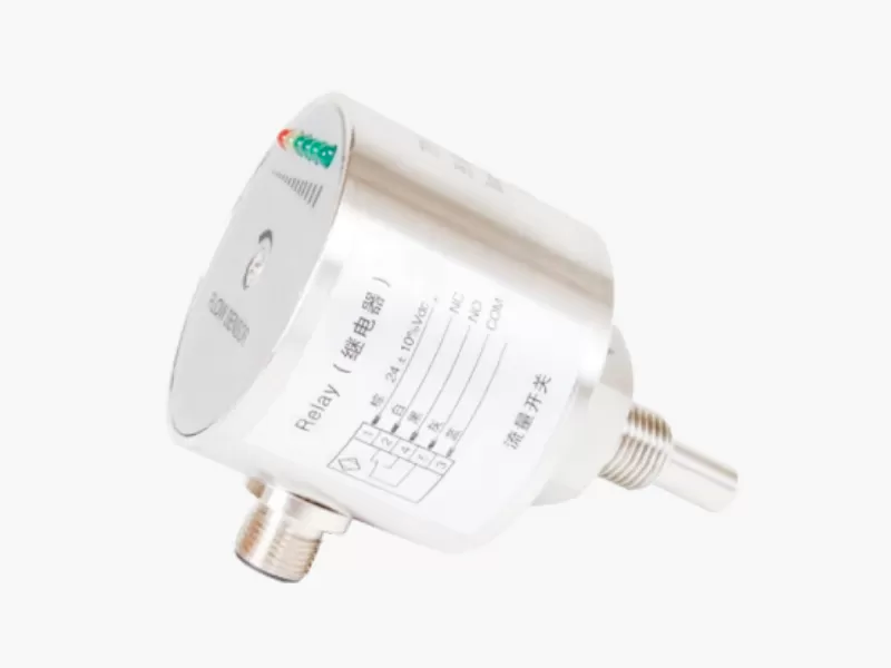
LEFOO FS213 is a stainless thermal electronic flow switch for water, oil or gas by variant. The distinction between a flow, pressure, temperature, protective or remote-actuator contact matters when selecting replacements.
Model Identification & Key Specifications
Original Manufacturer Data
FS213 thermal electronic flow switch uses heated/reference element and no mechanical piston, same maker flow velocity range 1–150cm/s water, 3–300cm/s oil, 20–2000cm/s gas but MUST not copy FS211 4A relay rating: FS213 maker lists 1A at 24V AC/DC relay and 400mA transistor, 24V±20%DC only. Steel probe AND stainless housing versus FS211 PBT body; 100bar proof, IP67, up to 8s power-on initiation and typically 2s response.
Confirm the manufacturer original model/order suffix, correct operating medium and mounting, switched load and power supply, safety device architecture, verified original maker photograph and applicable current approval documentation. Use the latest model-specific manufacturer technical references and correct photographs.
AirAlign Engineering & Variant Comparison
FS213 has stainless probe and housing, unlike the FS211 PBT body. Its 1 A relay must NOT inherit an FS211 4 A relay figure. Power-on initialization time and fluid-dependent velocity range matter for protective pump interlocks.
Always identify whether the part measures a continuously variable signal, provides a discrete protective trip or controls an operating cycle. Component substitution should preserve sensing topology, switching hysteresis, reset and energized/deenergized states. Enclosure and cable routing must be assessed within the actual equipment, not only against a standalone catalogue illustration.
Installation and Integration Checks
Check supply voltage, relay versus transistor wiring, contact NO/NC state and peak inductive duty. Signal outputs are not equivalent to motor-control contacts.
Distinguish temperature difference from independent thermal limits, and paddle/piston/calorimetric flow measurement from pressure differential. Match actual calibration media.
Mount as specified for the device’s reference sensor or mechanical paddle; verify working medium, housing, ingress protection, maximum process temperature and cable/port fittings.
Confirm applicable safety function and approvals for the exact order-code revision. Match any applicable CE, UL or TÜV documentation to the exact device configuration.
Related Products
LEFOO FS211 · LEFOO FS200 · LEFOO manufacturer profile
Official Manufacturer Sources
Independent AirAlign engineering page. Device-specific maker photo and current exact-variant third-party approvals require separate verification.
FS213 — stainless thermal sensor and cleaning
FS213 uses a stainless thermal sensing assembly intended for water, oil or gas in manufacturer-defined versions. Probe length, process fitting and wetted material suitability are key differences to assess against FS211; stainless housing alone does not guarantee any particular chemical resistance or hygiene standard. Select a flow threshold in the correct medium’s velocity range and check the output’s load rating and response after heating/cleaning cycles. A no-flow trip must be tested under actual process temperature.