LEFOO LFUD105
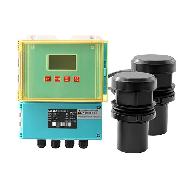
Original maker LEFOO LFUD105 Ultrasonic Differential Level Meter. This named model has different physical design/ultrasonic application from sibling LFUD models and must not be conflated across product suffixes.
Manufacturer technical and installation distinctions
| Principle | Two-probe ultrasonic difference in water level upstream/downstream screening |
|---|---|
| Range/blind zone | 0–3 to 25 m; blind zone 0.25–0.8 m |
| Accuracy/resolution | ±0.5% FS; 1mm |
| Outputs | Two 4–20mA + RS485 and 2 relay outputs; four-wire system |
| Environmental | IP65, separated ultrasonic probes ABS/PTFE options; original maker lists 10–70m cable options |
| Original example | LFUD105 0–3m A4MD 0.5% 10 1 (selected maker catalogue sample) |
Original LEFOO Sensor Products catalog, ultrasonic table and photos (page 29 in printed booklet) · Original LEFOO LFUD105 option and ordering table · LEFOO source model directory
Verified manufacturer model existence, distinct specs and original photo location on 23 October 2026. Exact cropped original photo / certificate and all part-number combinations remain open.
LFUD105 — upstream/downstream level difference
LFUD105 uses two ultrasonic level heads to derive an upstream-versus-downstream level difference, for example across a water-treatment screen. The host must distinguish each head’s level signal and the computed difference; incorrect sensor order can invert a fouling alarm. Match each head’s blind zone, cable length and echo conditions before using the differential for equipment control. Relay and RS485 wiring needs the exact supplied four-wire configuration, and no individual head should be mistaken for a stand-alone complete differential system.
Engineering Selection and Field Verification — LFUD105
A differential ultrasonic level measurement uses two sensing positions, so sensor alignment, reference elevations and comparable measurement conditions are critical. In screening or treatment applications, the resulting level difference can indicate head loss, but only if both sensors share a properly defined datum. Inspect both echo paths for foam, turbulence and obstructions before attributing a changing difference to process resistance.
During a LFUD105 installation, check the exact manufacturer’s order suffix and measure or document the input supply before connecting field wiring. Compare the range chosen on the purchase order to the connected control-system input scaling; a family data sheet can cover many configurations that are not interchangeable. Where the instrument reports a percentage-of-full-scale accuracy, calculate the corresponding absolute error at the selected span rather than treating it as a constant percentage of the current value. Record the installation location, sensor reference, associated output channels and expected maintenance access for later troubleshooting.
These engineering considerations do not add an unverified performance rating to the manufacturer table. Use the latest model-specific installation and operating instructions for final commissioning and safety decisions.