LEFOO LFT6720
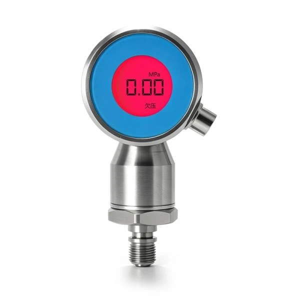
Model-specific technical information follows the manufacturer’s original product listing. Every range, interface, wetted material, option, configuration and regional approval must be checked against current ordered documents.
Manufacturer-published specifications
| Principle | High-overload glass-micro-melt digital pressure core; axial/radial options with LCD alarm backlight |
|---|---|
| Range | 0–10…60 MPa, maker-listed selection |
| Accuracy | ±0.5% FS; <0.3% FS per year stability |
| Output | RS485 / Modbus-RTU |
| Power and connector | 10–30 VDC; M8 four-core aviation connector |
| Temperature | −10 to +60°C operating; IP67 |
Original LEFOO LFT6720 model page and technical documentation · Official manufacturer document library
LFT6720 — digital pressure and alarm display
LFT6720 uses a glass micro-melt pressure sensor and an illuminated status display with RS485/Modbus RTU. Its display alarms require an explicit setpoint/fault program and should not automatically be treated as independent process safety cutouts. The host needs matching serial registers, pressure reference and full-scale range from the order code; a 10–60 MPa portfolio span is not one configurable cell. Confirm the selected alarm settings, electrical output and ordered configuration with current manufacturer documentation.
Engineering Selection and Field Verification — LFT6720
Its backlit status display and RS485 output offer convenient commissioning feedback, but the visual alarm is not by itself a certified process shutdown function. Confirm the exact Modbus register addresses, byte order, communication settings and pressure engineering units for the connected controller. The high-pressure sensor must be selected for its individual range, overload limit and process fitting.
During a LFT6720 installation, check the exact manufacturer’s order suffix and measure or document the input supply before connecting field wiring. Compare the range chosen on the purchase order to the connected control-system input scaling; a family data sheet can cover many configurations that are not interchangeable. Where the instrument reports a percentage-of-full-scale accuracy, calculate the corresponding absolute error at the selected span rather than treating it as a constant percentage of the current value. Record the installation location, sensor reference, associated output channels and expected maintenance access for later troubleshooting.
These engineering considerations do not add an unverified performance rating to the manufacturer table. Use the latest model-specific installation and operating instructions for final commissioning and safety decisions.