LEFOO / Environmental Transmitters
LEFOO LFH51
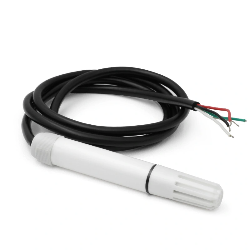
Probe-type humidity and temperature transmitter for duct or equipment measurement. The model is listed in LEFOO’s official downloadable technical document index.
Manufacturer: LEFOO
Official Technical Datasheet
LEFOO original datasheet catalog — search model LFH51 →
Accuracy, measurement range, electrical outputs, probe length and installation environment depend on variant and current revision. Check manufacturer data prior to equipment specification.
LFH51 remote probe integration
For the LFH51 probe-type architecture, determine the probe dimensions, allowable sensing temperature, probe-cable length and enclosure rating separately. Long cable, EMI and poor sensor exposure can increase effective system uncertainty even if the core RH sensing element is accurate. Ensure the controller understands both humidity and temperature channel scale, and distinguish a remote probe from an integrated wall-mount LFH10.
LFH51 — separate digital probe and signal selection
| Humidity | 0–100% RH with ±3% RH accuracy specified at 20°C and 60% RH. |
|---|---|
| Temperature | Digital sensor, ±0.3°C at 20°C by manufacturer model page. |
| Signal and supply | RS485 Modbus or 0–10 V, 12–36 VDC input; no 4–20 mA option listed for LFH51 itself. |
| Housing | PC probe shell and IP65 assembled protection. |
| Temperature and humidity exposure | −40 to +85°C, 5–95% RH non-condensing. |
Engineering note: The two output modes are alternatives, not simultaneous; do not transfer LFH10’s 4–20 mA connections to LFH51. Cable sealing and ventilation duct location affect real humidity response.
Original LEFOO model specification and order-selection reference (checked 26 October 2026).
Engineering Selection and Commissioning — LFH51
A probe-style humidity transmitter is sensitive to insertion depth and local flow. Select a representative duct or chamber position away from condensation, heater outlets and direct water spray. Mounting hardware should protect the probe from vibration and allow removal for service. Verify the output’s temperature/humidity mapping and any available filter cap against the actual dust load; a clogged sensor shield can slow response even when the sensing element is functional.
Review the exact LFH51 order code for the intended process, electrical output and measurement range. Note which parameters are manufacturer-declared family options rather than guaranteed features of every suffix. Before routine operation, verify correct supply wiring, engineering units and readings at practical test points. Record the installation conditions and any reference measurement so later drift or control-system errors can be investigated. Maintain access to the maker’s current operating instructions, particularly where variants use different connections or output protocols.
These engineering notes explain how to use the specification table; they do not certify an application or extend the published device limits.